
Working with Photoresistors (LDRs) on the Raspberry Pi with RNBO

In this article we'll cover how to use some simple sensors with RNBO on the Raspberry Pi target.
Photoresistors (LDRs)
Things you'll need:
- 1 x 1uf capacitor
- 1 x Light Dependent Resistor (aka Photoresistor)
- Breadboard
- Hook up wires
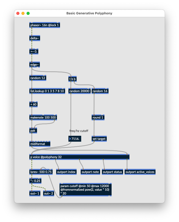
We'll start by exporting the following patcher to the Raspberry Pi target:
To control the cutoff parameter of this patcher with an LDR, we'll write a quick python script on the Raspberry Pi to use alongside the rnbo runner - ssh in, or connect up a keyboard. We'll use a library that should already be on your RPi image called gpiozero and another for communicating with the runner via OSC. You can use any OSC library you like, this example will use pyliblo3.
To install pyliblo3 run the following two commands from the terminal on your RPi.
$ sudo apt install liblo-dev
$ pip install pyliblo3
Now create a file called RNBOPi_LDR.py by using nano or any other text editor you prefer
$ nano RNBOPi_LDR.pyPaste in the following script, then save the file.
from gpiozero import LightSensor
import liblo as OSC
import sys, time

# send all messages to port 1234 on the local machine
try:
    target = OSC.Address(1234)
except OSC.AddressError as err:
    print(err)
    sys.exit()

# start the transport via OSC
OSC.send(target, "/rnbo/jack/transport/rolling", 1)

# read the sensor from GPIO pin 4
sensor = LightSensor(4)

try:
    while True:
        light_level = sensor.value
        print(light_level)
        OSC.send(target, "/rnbo/inst/0/params/cutoff/normalized", light_level)
        time.sleep(0.01)
except  KeyboardInterrupt:
    print("Exiting cleanly...")
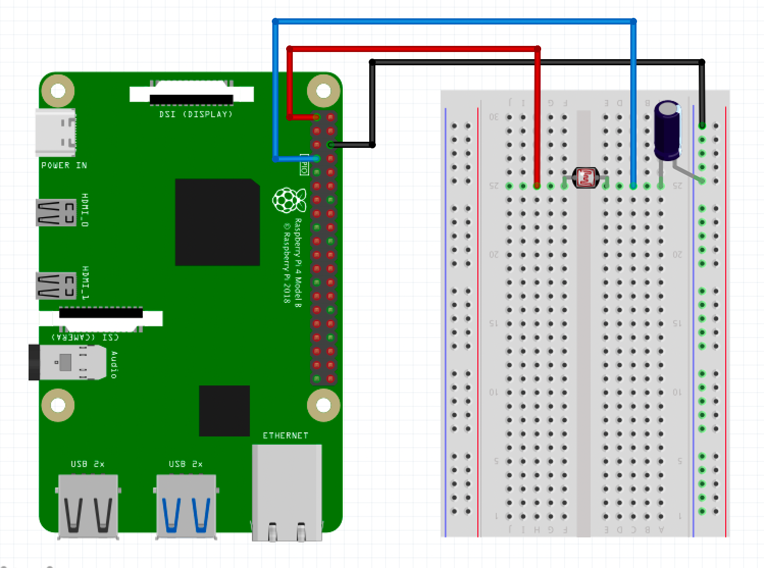
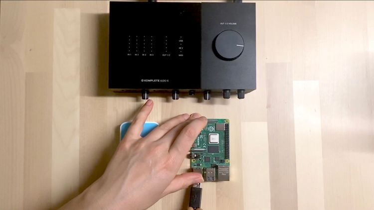
Now sudo poweroff the RPi, and disconnect the power. Let's create our circuit:
- 3.3v (red) from the RPi connects to one side of the LDR
- GND (black) from the RPi connects to the ground bus rail
- The 1uf capacitor connects the shorter leg to the ground bus rail, the longer leg connects to the terminal strip inline with the LDR
- RPi GPIO 4 (blue) connects in between the LDR and the capacitor
The sensor.value from the LDR is already normalized - so we can use this directly to control the cutoff parameter via the normalized osc address. If you take a look in the patcher, you will see there is some logarithmic scaling of this via @fromnormalized which makes it feel more natural.
Switch the Pi back on and at the terminal run the script:
$ python RNBOPi_LDR.pyNow grab a torch and voila! You should be opening up and closing the filter with your light source.

Member discussion