
Using a Gyroscope + Accelerometer module with RNBO on the RPi
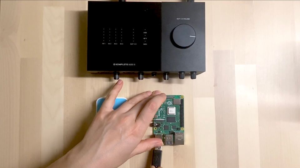
An Inertial Measurement Unit (IMU) is a common module to use with microcontrollers for measuring tilt and rotation. They're small and are perfect for use in wearable technology and robotics projects. In this article we'll use an MPU6050 with the i2c protocol and get it talking to some parameters in our RNBO patcher on the Raspberry Pi.
Things you'll need:
- An MPU6050 module
- Hook up wires
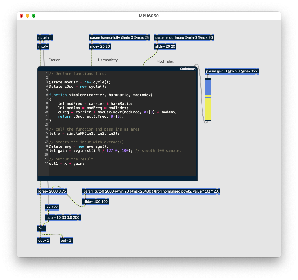
We'll start by exporting the following patcher to the Raspberry Pi target:
ssh in, or connect up a keyboard and monitor. To make things simple we'll utilise a Python module that performs all of the communication and processing. Install it using the following terminal commands:
$ sudo apt install python3-smbus
$ pip install mpu6050-raspberrypi
You'll likely already have python3-smbus already, but it doesn't hurt to check. We'll also need an OSC module for communicating with the runner via OSC. You can use any OSC library you like, this example will use pyliblo3.
$ sudo apt install liblo-dev
$ pip install pyliblo3
Now we'll need to enable i2c on the RPi. sudo raspi-config will bring up the config menu. Select "Interfacing Options" and then "i2c". Enable it, then when prompted select "No" for rebooting your RPi. We're going to power off the RPi and connect up our module. Exit the config menu without rebooting then at the terminal:
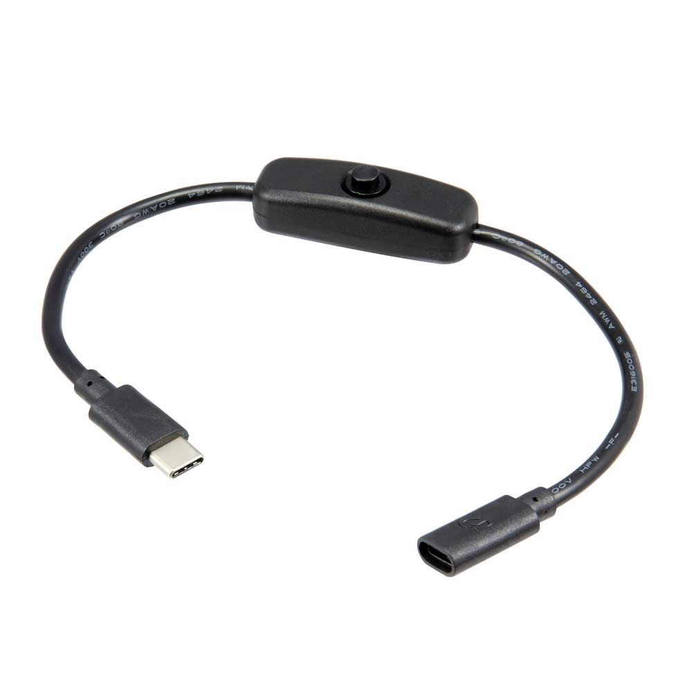
$ sudo poweroffIt's a good idea to only make connections to the RPi when powered off. Wait about 10 seconds then remove the power cable. I find these inline power switches to be pretty handy.
Connecting the module
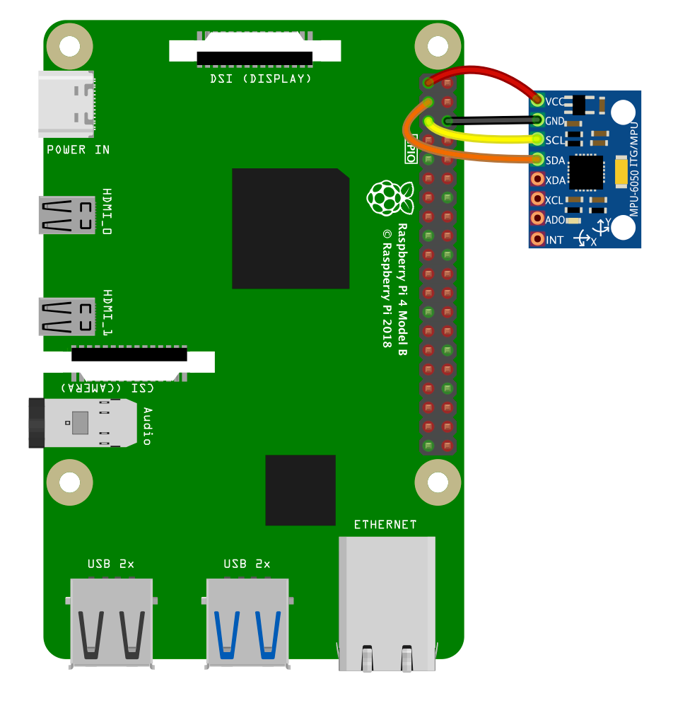
Now connect up the MPU6050 like so:
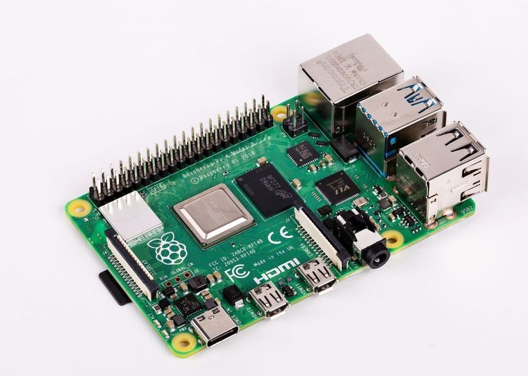
3.3v(red) from the RPi connects to theVCCon the moduleGND(black) from the RPi connects to theGNDon the moduleSCL(yellow) from the RPi to theSCLon the moduleSDA(orange) from the RPi to theSDAon the module
With this all connected up, power on the RPi. Once it's booted, we can check if the module is connected and available using this terminal command:
$ i2cdetect -y 1You should see the following, which shows the module's address in hexadecimal (0x68).
     0  1  2  3  4  5  6  7  8  9  a  b  c  d  e  f
00:          -- -- -- -- -- -- -- -- -- -- -- -- --
10: -- -- -- -- -- -- -- -- -- -- -- -- -- -- -- --
20: -- -- -- -- -- -- -- -- -- -- -- -- -- -- -- --
30: -- -- -- -- -- -- -- -- -- -- -- -- -- -- -- --
40: -- -- -- -- -- -- -- -- -- -- -- -- -- -- -- --
50: -- -- -- -- -- -- -- -- -- -- -- -- -- -- -- --
60: -- -- -- -- -- -- -- -- 68 -- -- -- -- -- -- --
70: -- -- -- -- -- -- -- --
If your module isn't showing up, you can use these two commands to disable then reenable the I2C driver without rebooting:
$ sudo rmmod i2c_dev
$ sudo modprobe i2c_dev
Let's create a python script to run that will communicate with the RNBO runner and the module.
$ nano RNBO_MPU6050.pyfrom mpu6050 import mpu6050
from time import sleep
import liblo as OSC
import sys
# send all messages to port 1234 on the local machine
try:
target = OSC.Address(1234)
except OSC.AddressError as err:
print(err)
sys.exit()# start the transport via OSC
sensor = mpu6050(0x68)
try:
while True:
accel_data = sensor.get_accel_data()
gyro_data = sensor.get_gyro_data()
temp = sensor.get_temp()
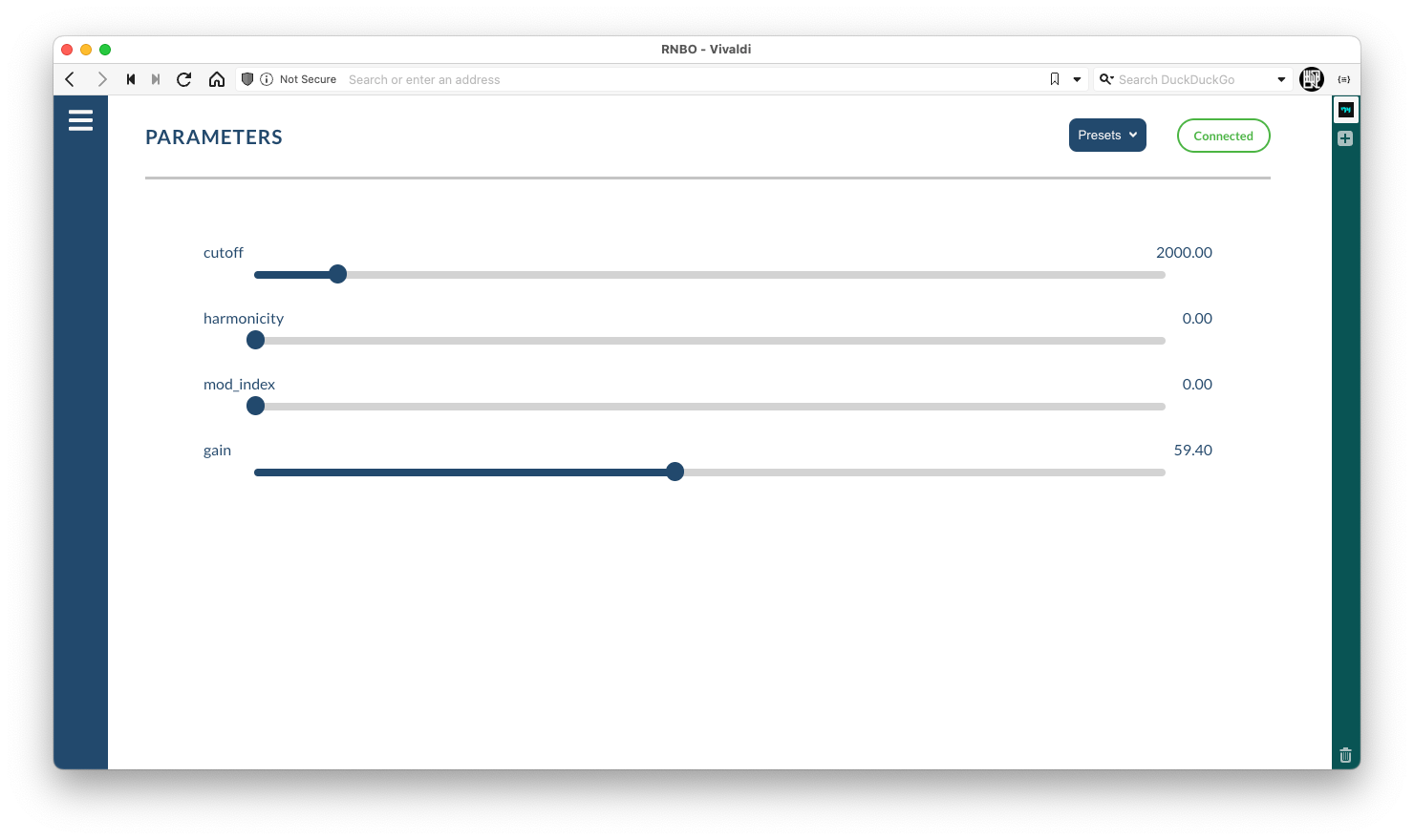
OSC.send(target, "/rnbo/inst/0/params/harmonicity/normalized", abs(accel_data["x"]) / 9.80665)
OSC.send(target, "/rnbo/inst/0/params/mod_index/normalized", abs(accel_data["y"] / 9.80665)
OSC.send(target, "/rnbo/inst/0/params/cutoff/normalized", abs(accel_data["z"] / 9.80665)print("Accelerometer data")print("x", accel_data["x"], "y", accel_data["y"], "z", accel_data["z"])print("Gyroscope data")print("x", gyro_data["x"], "y", gyro_data["y"], "z", gyro_data["z"])print("Temp:", temp, " Celcius")
sleep(0.1)
print("\033c", end="") #wipe screen
except KeyboardInterrupt:
print("Exiting cleanly...")In this example script we're only using values from the Accelerometer data to read the tilt angle of the module and assign them to the parameters. We're dividing the absolute value of each reading by 9.80665 (the approximate, average acceleration of gravity in metres per second, squared) to get a normalized value between 0 ... 1 to use with each parameter. This means the parameter will be at the minimum value when the sensor is placed flat - and move to the end of the parameter range when the sensor is tilted in either direction.
Instead of abs() you could divide the sensor value by 9.80665, add 1 then divide by 2 to map the entire tilt range to the parameter range, if you want to control the sound by tilting the module all the way around.
Running the script
To run the python script:
$ python RNBO_MPU6050.py
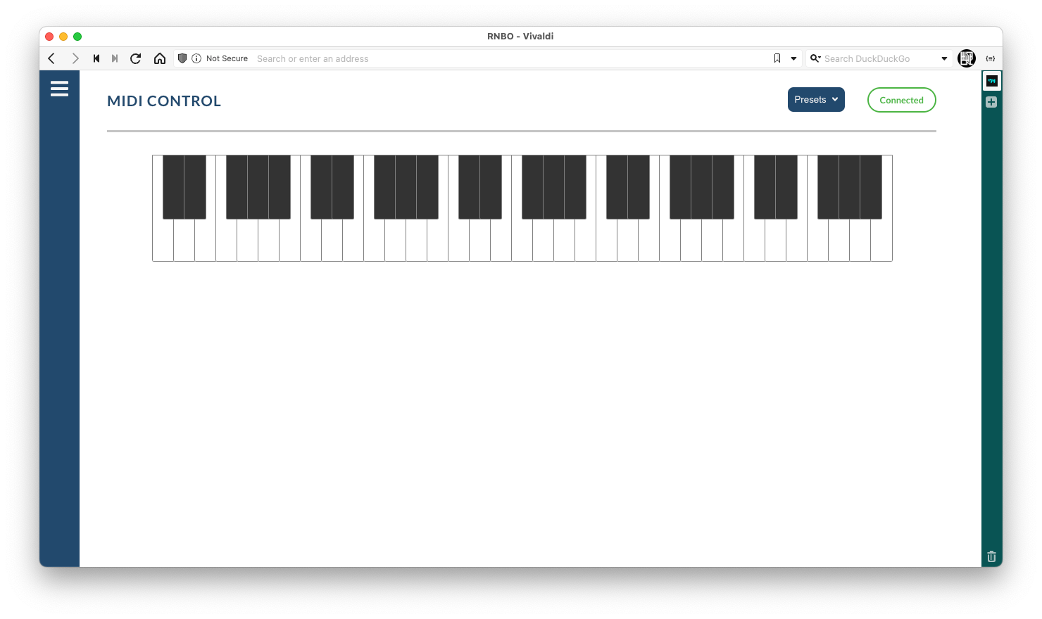
You should see the sensor values on the screen. The patcher needs a MIDI note to trigger a sound, you can use the Raspberry Pi Debug Interface to trigger a MIDI note from your browser if you don't have a MIDI controller connected. Don't forget to adjust the gain in the parameter menu first!


Member discussion